Raw graphics output on Linux: Part 2
In Part 1 of this series, we set up a command-line Linux in the VirtualBox emulator with support for direct frame buffer access, the git version control system and the clang compiler. Now let's use this to draw graphics to the screen by hand.
Getting the code
The code we'll be using is on my Github. So check it out, e.g. by doing:
mkdir ~/Programming
cd ~/Programming
git clone 'https://github.com/uliwitness/winner.git'
Now you'll have a winner folder in a Programming folder inside your home folder. Lets build and run the code:
cd winner
make
sudo ./winner
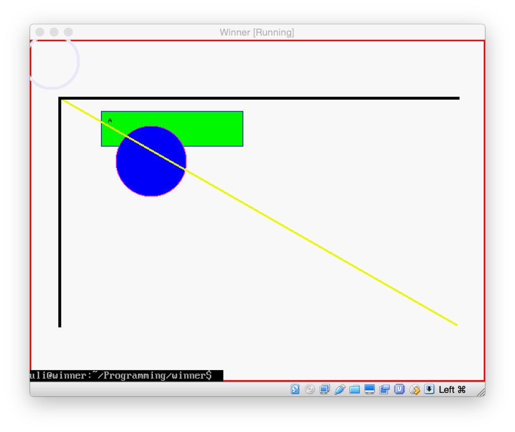
This code just drew a few shapes on the screen and then immediately quit. The Terminal was rather surprised about that, so just prints its last line on top of that.
How to access the screen
It took me a bit of googling, but eventually I found out that, to draw on the screen in Linux, you use the framebuffer. As most things in Linux, the frame buffer is a pseudo-file that you can just open and write to. This pseudo-file resides at /dev/fb0, and is the whole reason for the extra hoops we jumped through in Part 1 because a minimal Ubuntu doesn't have this file.
So if you look at the file linux/framebuffer.hpp in our winner subversion repository, it simply opens that file and maps it into memory, using the ioctl() function and some selector constants defined in the system header linux/fb.h to find out how large our screen is and how the pixels are laid out.
This is necessary, as at this low level, a screen is simply a long chain of bytes. Third row chained after second row after first row. Each row consists of pixels, which consist of R, G, B and optionally alpha components.
By mapping it into memory, we can use the screen just like any other block of memory and don't have to resort to seek() and write() to change pixels on the screen.
Esoterica
Since computers are sometimes faster when memory is aligned on certain multiples of numbers, and you also sometimes want to provide a frame buffer that is a subset of a bigger one (e.g. if a windowed operating system wanted to launch a framebuffer-based application and just trick it into thinking that the rectangle occupied by its window was the screen), the frame buffer includes a line length, x-offset and y-offset.
X and Y offset effectively shift all coordinates, so define the upper left corner of your screen inside the larger buffer. They're usually 0 for our use case.
The line length is the number of bytes in one row of pixels, which may be larger than the number of pixels * number of bytes in one pixel, because it may include additional, unused filler bytes that the computer needs to more quickly access the memory (some computers access memory faster if it is e.g. on an even-numbered address).
Actually drawing into the frame buffer
The actual drawing code is in our image class, which doesnt know about frame buffers. It just knows about a huge block of memory containing pixels, and its layout.
The main method in this class is set_pixel() which calculates a pointer to the first byte of a pixel at a given coordinate, and then, depending on the bit depth of the pixels in the bitmap, composes a 2-byte (16 bit) or 4-byte (32 bit) color value by filing out the given bits of our buffer.
All other drawing methods depend on this one:
Drawing rectangles
If you look at fill_rect, it simply takes a starting point (upper left corner of the rectangle) and then fills rows of pixels with that color.
To draw a frame around a rectangle is almost the same. We simply fill as many top and bottom rows as our line width dictates, and the rows in between get filled with a pixel (or whatever our line width is) at the left and right of our rectangle.
Drawing lines
Drawing one-pixel lines involves a tad of basic maths, but it's nothing that you couldn't get from a quick glance at Wikipedia. You take the line equation called the point-slope-form.
Then you calculate the line's slope based on your start and end point. If the line is more horizontal than vertical, you loop over the X coordinate from start to end and use that and the slope to calculate the corresponding Y. If it is more vertical than horizontal, you loop over the Y coordinate to get the X instead.
Now, if you use this naïve approach, you may get small gaps in the line, because lines work with fractional numbers, while our computer screen only has full, integer pixels. This is why this example uses a variation on the same process that was invented by someone named Bresenham, which keeps track of the loss of precision and adds pixels in as needed.
Now drawing a line of more than one pixel width is a little harder. You see, lines are really infinitely thin, and don't have a width. When you draw a line of a certain width, what computers usually do is either draw a rotated rectangle that is centered over the line and is as long as it is, and as wide as your line width, or it simply rubber-stamps a filled square or circle of the line width centered over each point on the line, which gives a similar look.
I essentially go with the latter approach in this example, but since I plan to eventually support different opacity for pixels, I do not want to draw whole boxes each time, because they would overlap and a 10% opaque line would end up 20% opaque in every spot where they overlap. So I just detect whether a line is mainly horizontal or vertical, then draw a horizontal or vertical 1 pixel line of the line width through each point.
This isnt quite perfect and gives diagonal lines a slanted edge, and makes them a bit too wide, so I eventually plan to at least change the code so the small lines are drawn at a 90° angle to the actual line youre drawing. But thats not done yet.
Drawing circles
Again, I just get the equation for circles off Wikipedia. It says that r2 = (x-centerX)2+(y-centerY)2. Where r is the radius of the circle you want to draw, x and y are the coordinates of any point which you want to test whether it is on the circle, and centerX and centerY are the center of the circle.
Once you know that, you can draw a circle like you draw a rectangle. You calculate the enclosing rectangle of our circle (by subtracting/adding the radius from/to the center point) and then, instead of just drawing the rectangle, you insert each point into the circle equation. If the right-hand-side equates to r2 or less, the point is in the circle, and you can draw it, otherwise you skip this point.
Drawing the outline of a circle is just a specialized version of filling it here. Instead of checking whether the equation comes up as < r2, you also check whether it is greater than (r -lineWidth)2. So essentially youre checking whether a point lies between two circles, the inner edge of your outline, and the outer edge of it.
This is probably not the optimal way to draw a circle, but it looks decent and is easy enough to understand. There are many tricks. For example, you could calculate only the upper right quarter of the circle, then flip the coordinate horizontally and vertically around the center and thus draw 4 points with every calculation. Bresenham even came up with an algorithm where you only calculate 1/8th of a circle's pixels.
Ovals
The library doesn't do ovals yet, but I think they could be implemented by using the circle equation and multiplying the coordinate of the longer side of the surrounding rectangle by the ratio between width and height. That way, your coordinates are projected onto a square, in which you can use the circle equation.
There are probably more efficient ways to do this.
Drawing bitmaps and text
To draw a bitmap (or rather, a pixel map) is basically a special case of rect drawing again. You take a buffer that already contains the raw pixels (like letterA in our example main.cpp). For simplicity, the code currently assumes that all images that you want to draw to the screen use 32-bit pixels. That also allows us to have a transparency value in the last 8 bits.
It simply draws a rectangle that is the size of the image, but instead of calling set_pixel() with a fixed color, it reads the color from the corresponding pixel in the pixel buffer we are supposed to draw. It also only draws pixels that are 100% opaque.
Text drawing is now simply a special case of this. You create a bitmap for every letter, then when asked to draw a certain character, load the corresponding bitmap and draw that. Of course, serious text processing would be more complex than that, but that is the foundational process as far as a drawing engine is concerned.
You'd of course need a text layout engine on top of that to handle wrapping, and other code to e.g. combine decomposed characters. Also, if you wanted to support the full Unicode character set (or even just all Chinese glyphs), you'd probably want to make your look-up happen in a way that you don't need to load all bitmaps immediately, but can rather lazy-load them as they are used.
Clipping
For a window manager, we need to be able to have windows overlap. To do that, we need to be able to designate areas as covered and have set_pixel() just not draw when asked to draw into those. That's what is commonly known as "clipping".
The general approach is to have a bitmap (i.e. a pixel buffer whose pixels only occupy 1 bit, on or off) of the same size as our pixel buffer. This bitmap indicates which pixels may be drawn into (usually thats called a mask).
There are of course various optimizations you can apply to this. The original Macintosh's QuickDraw engine used a compressed form of a bitmap called a Region, which simply contained entries for pixels in each line indicating the length of each color. I.e. 5 pixels off, 10 pixels full. Some graphics engines simply only allow to clip to rectangles (which can be described by 4 coordinates). If all your windows are rectangular, that is sufficient.
As a side effect, adding support for clipping means that you will catch if you draw outside the image's defined area using set_pixel(), instead of corrupting memory.
In addition, we can nest our drawing surfaces (the image class), giving us a dedicated coordinate system for each window. Even better, as all windows' images have a reference to the screen's frame buffer, it is comparatively cheap to create additional windows for additional local coordinate systems. Each button could be a window of its own, without needing a copy of the portion of frame buffer it occupies.
As clipping is a common operation in drawing code, our example provides two clipping masks: One for use by the client application, and one for use by the system to clip away areas covered by windows above this one. Only if both masks are black at a given coordinate will a point actually be drawn.
And that's it?
For a drawing library, this is basically all we need to implement a traditional 80ies-style software-rendered windowing system. Of course, if we wanted to actually implement a window manager, we would now need to implement a "window server" process that all applications can talk with to create windows and upload new drawings into them, and which coordinates between all applications' windows. Or we could provide our drawing calls via this server's protocol and thus do all the drawing in our server process.
And for real-world uses, you'd probably also want to process mouse movement and keep track of the mouse position and draw a cursor in its own little window on top of it all, and whenever the mouse button is pressed, find out which window was below the cursor at the time, and which process that window belongs to, and send a message to that process telling it where a click happened. Or forward touch events from your tablet's touch screen.
How do modern drawing systems work?
Modern drawing systems fundamentally work the same way, except that they usually draw partial pixels as well. That is, if a line passes through half of a screen pixel, they draw a 50% opaque pixel there, to avoid the "aliasing" "stair steps" that occur at the edges of diagonal lines or circles. This makes the image a little fuzzy, but also smoothes out these steps.
Also, the clipping and compositing of windows is usually handed off to the graphics card these days. You simply give the graphics card a buffer containing your window contents (the actual drawn shapes), and it will draw each window on top of the other at the requested positions, with the correct overlapping, using the graphics card's processor instead of your PC's central processing unit. The graphics card's processor has many cores doing work on it, and is therefore much faster at drawing our images on top of each other and accounting for transparency, as it can perform the calculations for many pixels at once, each on its own processor core.
Some graphics cards can even perform drawing operations on these cores, like our circle drawing code.